ESP8266使用IIC通信的LCD1602/2004转接板和0.96寸128*64 OLED液晶屏
ESP8266用来点亮小屏幕,手里面正好有两种显示屏,分别是LCD1602/2004字符液晶屏和0.96寸的OLED液晶屏,实现的过程倒是很简单,就一篇写两个了,不分开写了。
LCD1602/2004加I2C/IIC转换板
在esp8266中直接连接驱动,是没有任何问题的,这里我买了块IIC I2C接口的转换板,如下图。esp8266的IO口本来就很少了,还要占用需要7个IO口来显示屏幕,使用了转换板,可以减少使用5个IO口。
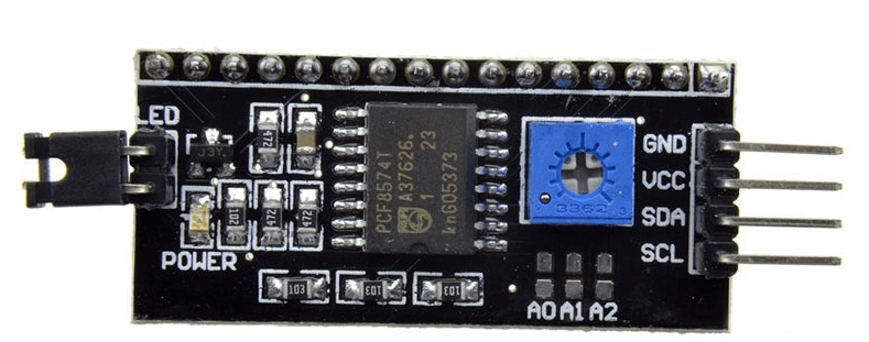
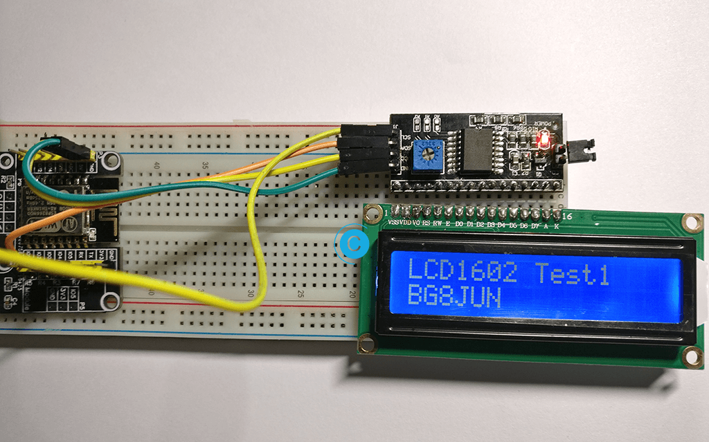
屏幕的连接就对着转换板就是,线路的连接如下:
- SCL串行时钟连接到IO5
- SDA串行数据连接到IO4
其他的注意事项:
- 带背光电源控制,可以通过跳线帽设置是否连接背光电源。插上跳线帽为连接背光电源,拔掉跳线帽为断开背光电源
- 对比度可调节,旋转蓝色电位器,顺时针增强,逆时针减弱。电位器设计在正面,方便客户随时随地自由调节
- 模块可级联,最多可级联8个。通过短路A0/A1/A2修改设备地址
使用的库是LiquidCrystal_I2C
如果事先不知道地址的话,需使用文末的例程来得到。在这里我的地址是:0x3F
#include <LiquidCrystal_I2C.h>

LiquidCrystal_I2C lcd(0x3F,16,2);

void setup()
{
  lcd.init();
  lcd.backlight();
}

void loop()
{
  lcd.setCursor(0,0);
  lcd.print("LCD1602 Test1");
  lcd.setCursor(0,1);
  lcd.print("cyqsd");
  delay(1000);
}
不显字甚至没黑框说明了对比度调节不对,可以调可调电阻。
值得注意的是LiquidCrystal_I2C中的cpp需要修改一下,不然屏幕只能显示第一个字符。
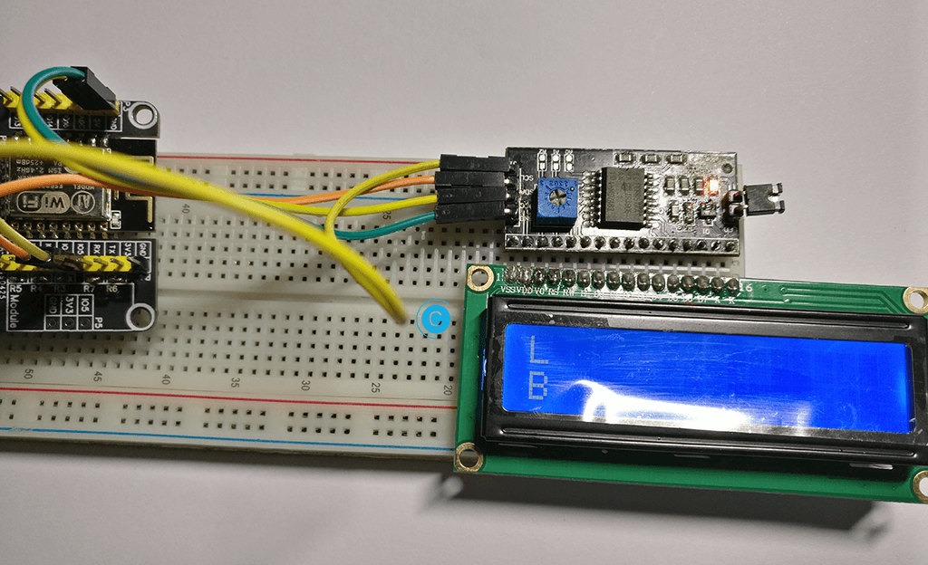
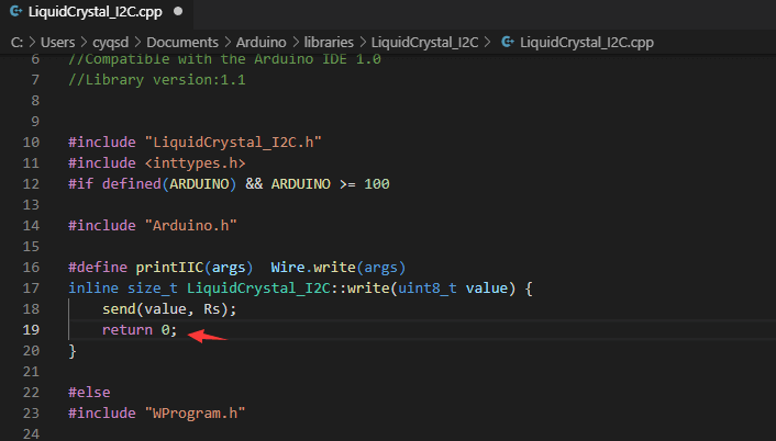
讲图中所示位置的return 0;改为return 1;
arduino 1.6.6版本IDE IIC 1602LCD 液晶 显示不正常 只显示第一个首字符!
0.96寸 I2C IIC通信 128*64 OLED液晶屏模块
如果是使用的模块是arduino,那么使用的库是U8glib,几乎涵盖了绝大多数的常见TFT和OLED显示屏,能解决许多不必要的问题。esp8266则不兼容,下面会说。如果需要显示汉字则需要取模。购买的屏幕是SSD1306的主控,分辨率为128X64。

也可以上一下Github看。
U8glib将不再开发。提示使用u8g2。
The Arduino library U8g2 can be installed from the library manager of the Arduino IDE. U8g2 also includes U8x8 library:
U8g2
- Includes all graphics procedures (line/box/circle draw).
- Supports many fonts. (Almost) no restriction on the font height.
- Requires some memory in the microcontroller to render the display.
U8x8
- Text output only (character) device.
- Only fonts allowed with fit into a 8x8 pixel grid.
- Writes directly to the display. No buffer in the microcontroller required.
这里搜索到屏幕的地址是:0x3C
Scanning...
I2C device found at address 0x3C !
done我们在这里只需要找到自己的OLED屏幕就好了,取消前面的注释。U8GLIB_SSD1306_128X64 u8g(U8G_I2C_OPT_NONE);
/*

  PrintTest.pde

  How to use the base class "Print"

  >>> Before compiling: Please remove comment from the constructor of the
  >>> connected graphics display (see below).

  Universal 8bit Graphics Library, https://github.com/olikraus/u8glib/

  Copyright (c) 2012, olikraus@gmail.com
  All rights reserved.

  Redistribution and use in source and binary forms, with or without modification,
  are permitted provided that the following conditions are met:

  * Redistributions of source code must retain the above copyright notice, this list
    of conditions and the following disclaimer.

  * Redistributions in binary form must reproduce the above copyright notice, this
    list of conditions and the following disclaimer in the documentation and/or other
    materials provided with the distribution.

  THIS SOFTWARE IS PROVIDED BY THE COPYRIGHT HOLDERS AND
  CONTRIBUTORS "AS IS" AND ANY EXPRESS OR IMPLIED WARRANTIES,
  INCLUDING, BUT NOT LIMITED TO, THE IMPLIED WARRANTIES OF
  MERCHANTABILITY AND FITNESS FOR A PARTICULAR PURPOSE ARE
  DISCLAIMED. IN NO EVENT SHALL THE COPYRIGHT HOLDER OR
  CONTRIBUTORS BE LIABLE FOR ANY DIRECT, INDIRECT, INCIDENTAL,
  SPECIAL, EXEMPLARY, OR CONSEQUENTIAL DAMAGES (INCLUDING, BUT
  NOT LIMITED TO, PROCUREMENT OF SUBSTITUTE GOODS OR SERVICES;
  LOSS OF USE, DATA, OR PROFITS; OR BUSINESS INTERRUPTION) HOWEVER
  CAUSED AND ON ANY THEORY OF LIABILITY, WHETHER IN CONTRACT,
  STRICT LIABILITY, OR TORT (INCLUDING NEGLIGENCE OR OTHERWISE)
  ARISING IN ANY WAY OUT OF THE USE OF THIS SOFTWARE, EVEN IF
  ADVISED OF THE POSSIBILITY OF SUCH DAMAGE.

*/


#include "U8glib.h"

// setup u8g object, please remove comment from one of the following constructor calls
// IMPORTANT NOTE: The following list is incomplete. The complete list of supported
// devices with all constructor calls is here: https://github.com/olikraus/u8glib/wiki/device
//U8GLIB_NHD27OLED_BW u8g(13, 11, 10, 9);    // SPI Com: SCK = 13, MOSI = 11, CS = 10, A0 = 9
//U8GLIB_NHD27OLED_2X_BW u8g(13, 11, 10, 9);    // SPI Com: SCK = 13, MOSI = 11, CS = 10, A0 = 9
//U8GLIB_NHD27OLED_GR u8g(13, 11, 10, 9);    // SPI Com: SCK = 13, MOSI = 11, CS = 10, A0 = 9
//U8GLIB_NHD27OLED_2X_GR u8g(13, 11, 10, 9);    // SPI Com: SCK = 13, MOSI = 11, CS = 10, A0 = 9
//U8GLIB_NHD31OLED_BW u8g(13, 11, 10, 9);    // SPI Com: SCK = 13, MOSI = 11, CS = 10, A0 = 9
//U8GLIB_NHD31OLED_2X_BW u8g(13, 11, 10, 9);    // SPI Com: SCK = 13, MOSI = 11, CS = 10, A0 = 9
//U8GLIB_NHD31OLED_GR u8g(13, 11, 10, 9);    // SPI Com: SCK = 13, MOSI = 11, CS = 10, A0 = 9
//U8GLIB_NHD31OLED_2X_GR u8g(13, 11, 10, 9);    // SPI Com: SCK = 13, MOSI = 11, CS = 10, A0 = 9
//U8GLIB_DOGS102 u8g(13, 11, 10, 9, 8);        // SPI Com: SCK = 13, MOSI = 11, CS = 10, A0 = 9
//U8GLIB_DOGM132 u8g(13, 11, 10, 9);        // SPI Com: SCK = 13, MOSI = 11, CS = 10, A0 = 9
//U8GLIB_DOGM128 u8g(13, 11, 10, 9);        // SPI Com: SCK = 13, MOSI = 11, CS = 10, A0 = 9
//U8GLIB_DOGM128_2X u8g(13, 11, 10, 9);        // SPI Com: SCK = 13, MOSI = 11, CS = 10, A0 = 9
//U8GLIB_ST7920_128X64_1X u8g(8, 9, 10, 11, 4, 5, 6, 7, 18, 17, 16);   // 8Bit Com: D0..D7: 8,9,10,11,4,5,6,7 en=18, di=17,rw=16
//U8GLIB_ST7920_128X64_4X u8g(8, 9, 10, 11, 4, 5, 6, 7, 18, 17, 16);   // 8Bit Com: D0..D7: 8,9,10,11,4,5,6,7 en=18, di=17,rw=16
//U8GLIB_ST7920_128X64_1X u8g(18, 16, 17);    // SPI Com: SCK = en = 18, MOSI = rw = 16, CS = di = 17
//U8GLIB_ST7920_128X64_4X u8g(18, 16, 17);    // SPI Com: SCK = en = 18, MOSI = rw = 16, CS = di = 17
//U8GLIB_ST7920_192X32_1X u8g(8, 9, 10, 11, 4, 5, 6, 7, 18, 17, 16);   // 8Bit Com: D0..D7: 8,9,10,11,4,5,6,7 en=18, di=17,rw=16
//U8GLIB_ST7920_192X32_4X u8g(8, 9, 10, 11, 4, 5, 6, 7, 18, 17, 16);   // 8Bit Com: D0..D7: 8,9,10,11,4,5,6,7 en=18, di=17,rw=16
//U8GLIB_ST7920_192X32_1X u8g(18, 16, 17);    // SPI Com: SCK = en = 18, MOSI = rw = 16, CS = di = 17
//U8GLIB_ST7920_192X32_4X u8g(18, 16, 17);    // SPI Com: SCK = en = 18, MOSI = rw = 16, CS = di = 17
//U8GLIB_ST7920_192X32_1X u8g(13, 11, 10);    // SPI Com: SCK = en = 13, MOSI = rw = 11, CS = di = 10
//U8GLIB_ST7920_192X32_4X u8g(10);        // SPI Com: SCK = en = 13, MOSI = rw = 11, CS = di = 10, HW SPI
//U8GLIB_ST7920_202X32_1X u8g(8, 9, 10, 11, 4, 5, 6, 7, 18, 17, 16);   // 8Bit Com: D0..D7: 8,9,10,11,4,5,6,7 en=18, di=17,rw=16
//U8GLIB_ST7920_202X32_4X u8g(8, 9, 10, 11, 4, 5, 6, 7, 18, 17, 16);   // 8Bit Com: D0..D7: 8,9,10,11,4,5,6,7 en=18, di=17,rw=16
//U8GLIB_ST7920_202X32_1X u8g(18, 16, 17);    // SPI Com: SCK = en = 18, MOSI = rw = 16, CS = di = 17
//U8GLIB_ST7920_202X32_4X u8g(18, 16, 17);    // SPI Com: SCK = en = 18, MOSI = rw = 16, CS = di = 17
//U8GLIB_LM6059 u8g(13, 11, 10, 9);        // SPI Com: SCK = 13, MOSI = 11, CS = 10, A0 = 9
//U8GLIB_LM6063 u8g(13, 11, 10, 9);        // SPI Com: SCK = 13, MOSI = 11, CS = 10, A0 = 9
//U8GLIB_DOGXL160_BW u8g(10, 9);        // SPI Com: SCK = 13, MOSI = 11, CS = 10, A0 = 9
//U8GLIB_DOGXL160_GR u8g(13, 11, 10, 9);    // SPI Com: SCK = 13, MOSI = 11, CS = 10, A0 = 9
//U8GLIB_DOGXL160_2X_BW u8g(13, 11, 10, 9);    // SPI Com: SCK = 13, MOSI = 11, CS = 10, A0 = 9
//U8GLIB_DOGXL160_2X_GR u8g(13, 11, 10, 9);    // SPI Com: SCK = 13, MOSI = 11, CS = 10, A0 = 9
//U8GLIB_PCD8544 u8g(13, 11, 10, 9, 8);        // SPI Com: SCK = 13, MOSI = 11, CS = 10, A0 = 9, Reset = 8
//U8GLIB_PCF8812 u8g(13, 11, 10, 9, 8);        // SPI Com: SCK = 13, MOSI = 11, CS = 10, A0 = 9, Reset = 8
//U8GLIB_KS0108_128 u8g(8, 9, 10, 11, 4, 5, 6, 7, 18, 14, 15, 17, 16);         // 8Bit Com: D0..D7: 8,9,10,11,4,5,6,7 en=18, cs1=14, cs2=15,di=17,rw=16
//U8GLIB_LC7981_160X80 u8g(8, 9, 10, 11, 4, 5, 6, 7,  18, 14, 15, 17, 16);     // 8Bit Com: D0..D7: 8,9,10,11,4,5,6,7 en=18, cs=14 ,di=15,rw=17, reset = 16
//U8GLIB_LC7981_240X64 u8g(8, 9, 10, 11, 4, 5, 6, 7,  18, 14, 15, 17, 16);     // 8Bit Com: D0..D7: 8,9,10,11,4,5,6,7 en=18, cs=14 ,di=15,rw=17, reset = 16
//U8GLIB_LC7981_240X128 u8g(8, 9, 10, 11, 4, 5, 6, 7,  18, 14, 15, 17, 16);     // 8Bit Com: D0..D7: 8,9,10,11,4,5,6,7 en=18, cs=14 ,di=15,rw=17, reset = 16
//U8GLIB_ILI9325D_320x240 u8g(18,17,19,U8G_PIN_NONE,16 );              // 8Bit Com: D0..D7: 0,1,2,3,4,5,6,7 en=wr=18, cs=17, rs=19, rd=U8G_PIN_NONE, reset = 16
//U8GLIB_SBN1661_122X32 u8g(8,9,10,11,4,5,6,7,14,15, 17, U8G_PIN_NONE, 16);     // 8Bit Com: D0..D7: 8,9,10,11,4,5,6,7 cs1=14, cs2=15,di=17,rw=16,reset = 16
//U8GLIB_SSD1306_128X64 u8g(13, 11, 10, 9);    // SW SPI Com: SCK = 13, MOSI = 11, CS = 10, A0 = 9
//U8GLIB_SSD1306_128X64 u8g(4, 5, 6, 7);    // SW SPI Com: SCK = 4, MOSI = 5, CS = 6, A0 = 7 (new white HalTec OLED)
//U8GLIB_SSD1306_128X64 u8g(10, 9);        // HW SPI Com: CS = 10, A0 = 9 (Hardware Pins are  SCK = 13 and MOSI = 11)
//U8GLIB_SSD1306_128X64 u8g(U8G_I2C_OPT_NONE|U8G_I2C_OPT_DEV_0);    // I2C / TWI
//U8GLIB_SSD1306_128X64 u8g(U8G_I2C_OPT_DEV_0|U8G_I2C_OPT_NO_ACK|U8G_I2C_OPT_FAST);    // Fast I2C / TWI
//U8GLIB_SSD1306_128X64 u8g(U8G_I2C_OPT_NO_ACK);    // Display which does not send AC
//U8GLIB_SSD1306_ADAFRUIT_128X64 u8g(13, 11, 10, 9);    // SW SPI Com: SCK = 13, MOSI = 11, CS = 10, A0 = 9
//U8GLIB_SSD1306_ADAFRUIT_128X64 u8g(10, 9);        // HW SPI Com: CS = 10, A0 = 9 (Hardware Pins are  SCK = 13 and MOSI = 11)
//U8GLIB_SSD1306_128X32 u8g(13, 11, 10, 9);    // SW SPI Com: SCK = 13, MOSI = 11, CS = 10, A0 = 9
//U8GLIB_SSD1306_128X32 u8g(10, 9);             // HW SPI Com: CS = 10, A0 = 9 (Hardware Pins are  SCK = 13 and MOSI = 11)
//U8GLIB_SSD1306_128X32 u8g(U8G_I2C_OPT_NONE);    // I2C / TWI
//U8GLIB_SH1106_128X64 u8g(13, 11, 10, 9);    // SW SPI Com: SCK = 13, MOSI = 11, CS = 10, A0 = 9
//U8GLIB_SH1106_128X64 u8g(4, 5, 6, 7);    // SW SPI Com: SCK = 4, MOSI = 5, CS = 6, A0 = 7 (new blue HalTec OLED)
U8GLIB_SH1106_128X64 u8g(U8G_I2C_OPT_NONE);    // I2C / TWI
//U8GLIB_SH1106_128X64 u8g(U8G_I2C_OPT_DEV_0|U8G_I2C_OPT_FAST);    // Dev 0, Fast I2C / TWI
//U8GLIB_SH1106_128X64 u8g(U8G_I2C_OPT_NO_ACK);    // Display which does not send ACK
//U8GLIB_SSD1309_128X64 u8g(13, 11, 10, 9);    // SPI Com: SCK = 13, MOSI = 11, CS = 10, A0 = 9
//U8GLIB_SSD1327_96X96_GR u8g(U8G_I2C_OPT_NONE);    // I2C
//U8GLIB_SSD1327_96X96_2X_GR u8g(U8G_I2C_OPT_NONE);    // I2C
//U8GLIB_UC1611_DOGM240 u8g(U8G_I2C_OPT_NONE);    // I2C
//U8GLIB_UC1611_DOGM240 u8g(13, 11, 10, 9);    // SW SPI Com: SCK = 13, MOSI = 11, CS = 10, A0 = 9
//U8GLIB_UC1611_DOGM240 u8g(10, 9);        // HW SPI Com: CS = 10, A0 = 9 (Hardware Pins are  SCK = 13 and MOSI = 11)
//U8GLIB_UC1611_DOGXL240 u8g(U8G_I2C_OPT_NONE);    // I2C
//U8GLIB_UC1611_DOGXL240 u8g(13, 11, 10, 9);    // SW SPI Com: SCK = 13, MOSI = 11, CS = 10, A0 = 9
//U8GLIB_UC1611_DOGXL240 u8g(10, 9);        // HW SPI Com: CS = 10, A0 = 9 (Hardware Pins are  SCK = 13 and MOSI = 11)
//U8GLIB_NHD_C12864 u8g(13, 11, 10, 9, 8);    // SPI Com: SCK = 13, MOSI = 11, CS = 10, A0 = 9, RST = 8
//U8GLIB_NHD_C12832 u8g(13, 11, 10, 9, 8);    // SPI Com: SCK = 13, MOSI = 11, CS = 10, A0 = 9, RST = 8
//U8GLIB_LD7032_60x32 u8g(13, 11, 10, 9, 8);    // SPI Com: SCK = 13, MOSI = 11, CS = 10, A0 = 9, RST = 8
//U8GLIB_LD7032_60x32 u8g(11, 12, 9, 10, 8);    // SPI Com: SCK = 11, MOSI = 12, CS = 9, A0 = 10, RST = 8  (SW SPI Nano Board)
//U8GLIB_UC1608_240X64 u8g(13, 11, 10, 9, 8);    // SW SPI Com: SCK = 13, MOSI = 11, CS = 10, A0 = 9, RST = 8
//U8GLIB_UC1608_240X64_2X u8g(13, 11, 10, 9, 8);    // SW SPI Com: SCK = 13, MOSI = 11, CS = 10, A0 = 9, RST = 8
//U8GLIB_UC1608_240X64 u8g(10, 9, 8);    // HW SPI Com: SCK = 13, MOSI = 11, CS = 10, A0 = 9, RST = 8
//U8GLIB_UC1608_240X64_2X u8g(10, 9, 8);    // HW SPI Com: SCK = 13, MOSI = 11, CS = 10, A0 = 9, RST = 8
//U8GLIB_UC1608_240X u8g(13, 11, 10, 9, 8);    // SW SPI Com: SCK = 13, MOSI = 11, CS = 10, A0 = 9, RST = 8
//U8GLIB_UC1608_240X64_2X u8g(13, 11, 10, 9, 8);    // SW SPI Com: SCK = 13, MOSI = 11, CS = 10, A0 = 9, RST = 8
//U8GLIB_UC1608_240X64 u8g(10, 9, 8);    // HW SPI Com: SCK = 13, MOSI = 11, CS = 10, A0 = 9, RST = 8
//U8GLIB_UC1608_240X64_2X u8g(10, 9, 8);    // HW SPI Com: SCK = 13, MOSI = 11, CS = 10, A0 = 9, RST = 8
//U8GLIB_T6963_240X128 u8g(8, 9, 10, 11, 4, 5, 6, 7, 14, 15, 17, 18, 16); // 8Bit Com: D0..D7: 8,9,10,11,4,5,6,7, cs=14, a0=15, wr=17, rd=18, reset=16
//U8GLIB_T6963_128X128 u8g(8, 9, 10, 11, 4, 5, 6, 7, 14, 15, 17, 18, 16); // 8Bit Com: D0..D7: 8,9,10,11,4,5,6,7, cs=14, a0=15, wr=17, rd=18, reset=16
//U8GLIB_T6963_240X64 u8g(8, 9, 10, 11, 4, 5, 6, 7, 14, 15, 17, 18, 16); // 8Bit Com: D0..D7: 8,9,10,11,4,5,6,7, cs=14, a0=15, wr=17, rd=18, reset=16
//U8GLIB_T6963_128X64 u8g(8, 9, 10, 11, 4, 5, 6, 7, 14, 15, 17, 18, 16); // 8Bit Com: D0..D7: 8,9,10,11,4,5,6,7, cs=14, a0=15, wr=17, rd=18, reset=16
//U8GLIB_HT1632_24X16 u8g(3, 2, 4);        // WR = 3, DATA = 2, CS = 4
//U8GLIB_SSD1351_128X128_332 u8g(13, 11, 8, 9, 7); // Arduino UNO: SW SPI Com: SCK = 13, MOSI = 11, CS = 8, A0 = 9, RESET = 7 (http://electronics.ilsoft.co.uk/ArduinoShield.aspx)
//U8GLIB_SSD1351_128X128_332 u8g(76, 75, 8, 9, 7); // Arduino DUE: SW SPI Com: SCK = 13, MOSI = 11, CS = 8, A0 = 9, RESET = 7 (http://electronics.ilsoft.co.uk/ArduinoShield.aspx)
//U8GLIB_SSD1351_128X128_332 u8g(8, 9, 7); // Arduino: HW SPI Com: SCK = 13, MOSI = 11, CS = 8, A0 = 9, RESET = 7 (http://electronics.ilsoft.co.uk/ArduinoShield.aspx)
//U8GLIB_SSD1351_128X128_HICOLOR u8g(76, 75, 8, 9, 7); // Arduino DUE, SW SPI Com: SCK = 76, MOSI = 75, CS = 8, A0 = 9, RESET = 7 (http://electronics.ilsoft.co.uk/ArduinoShield.aspx)
//U8GLIB_SSD1351_128X128_HICOLOR u8g(8, 9, 7); // Arduino, HW SPI Com: SCK = 76, MOSI = 75, CS = 8, A0 = 9, RESET = 7 (http://electronics.ilsoft.co.uk/ArduinoShield.aspx)
//U8GLIB_SSD1351_128X128GH_332 u8g(8, 9, 7); // Arduino, HW SPI Com: SCK = 76, MOSI = 75, CS = 8, A0 = 9, RESET = 7 (Freetronics OLED)
//U8GLIB_SSD1351_128X128GH_HICOLOR u8g(8, 9, 7); // Arduino, HW SPI Com: SCK = 76, MOSI = 75, CS = 8, A0 = 9, RESET = 7 (Freetronics OLED)

void draw(void) {
  // graphic commands to redraw the complete screen should be placed here
  u8g.setFont(u8g_font_unifont);
  u8g.setPrintPos(0, 20);
  // call procedure from base class, http://arduino.cc/en/Serial/Print
  u8g.print("Hello World!");
}

void setup(void) {
  // flip screen, if required
  // u8g.setRot180();
}

void loop(void) {
  // picture loop
  u8g.firstPage();
  do {
    draw();
  } while( u8g.nextPage() );

  // rebuild the picture after some delay
  delay(500);
}
如果是esp8266则会出现如下的提示:
警告: U8glib 库要求运行在 (avr, sam) 架构(),可能与你现在运行在 (esp8266) 架构上的开发板()不兼容。
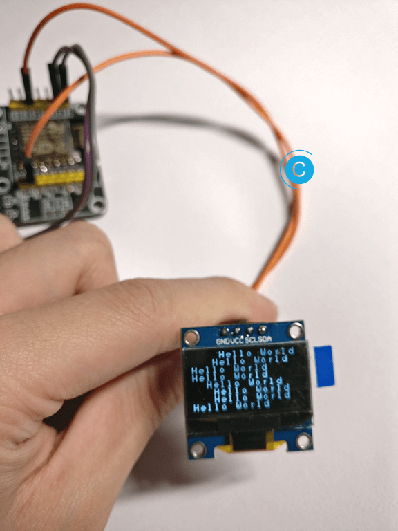
所以这里使用的是ESP8266-OLED_Display_Library库,其实内部原理肯定都是差不多的。
线路的连接是:
- SDA连接到IO2
- SCL连接到IO14
// Example sketch for testing OLED display

// We need to include Wire.h for I2C communication
#include <Wire.h>
#include "OLED.h"

// Declare OLED display
// display(SDA, SCL);
// SDA and SCL are the GPIO pins of ESP8266 that are connected to respective pins of display.
OLED display(2, 14);

void setup() {
  Serial.begin(9600);
  Serial.println("OLED test!");

  // Initialize display
  display.begin();

  // Test message
  display.print("Hello World");
  delay(3*1000);

  // Test long message
  display.print("Lorem ipsum dolor sit amet, consectetur adipiscing elit, sed do eiusmod tempor incididunt ut labore et dolore magna aliqua.");
  delay(3*1000);

  // Test display clear
  display.clear();
  delay(3*1000);

  // Test message postioning
  display.print("TOP-LEFT");
  display.print("4th row", 4);
  display.print("RIGHT-BOTTOM", 7, 4);
  delay(3*1000);

  // Test display OFF
  display.off();
  display.print("3rd row", 3, 8);
  delay(3*1000);

  // Test display ON
  display.on();
  delay(3*1000);
}

int r = 0, c = 0;

void loop() {
  r = r % 8;
  c = micros() % 6;

  if (r == 0)
    display.clear();

  display.print("Hello World", r++, c++);

  delay(500);
}
查找I2C显示屏地址
如果因为地址问题没有成功,可以使用下面的地址搜索Demo来搜索。
#include <Wire.h>


void setup()
{
Wire.begin();

Serial.begin(9600);
Serial.println("\nI2C Scanner");
}


void loop()
{
byte error, address;
int nDevices;

Serial.println("Scanning...");

nDevices = 0;
for(address = 1; address < 127; address++ )
{
// The i2c_scanner uses the return value of
// the Write.endTransmisstion to see if
// a device did acknowledge to the address.
Wire.beginTransmission(address);
error = Wire.endTransmission();

if (error == 0)
{
Serial.print("I2C device found at address 0x");
if (address<16)
Serial.print("0");
Serial.print(address,HEX);
Serial.println(" !");

nDevices++;
}
else if (error==4)
{
Serial.print("Unknow error at address 0x");
if (address<16)
Serial.print("0");
Serial.println(address,HEX);
}
}
if (nDevices == 0)
Serial.println("No I2C devices found\n");
else
Serial.println("done\n");

delay(5000); // wait 5 seconds for next scan
}
如果能够搜索到的话,串口会有如下的提示信息。
I2C Scanner
Scanning...
I2C device found at address 0x3F !
done本作品采用 知识共享署名-相同方式共享 4.0 国际许可协议 进行许可。