ESP8266使用MQTT连接阿里云物联网平台(官方NONOS_SDK和Arduino_IDE )
在前文的使用ESP8266自制廉价Gokit SOC方案,已经提到了很多关于ESP8266的简单使用,但是使用的机智云的平台,总觉得哪里不对。所以又折腾下另外一个平台,现在物联网的现状不就是这样吗,平台多如牛毛。本文讲的内容不是很多,主要就是两种不同的开发方式,从一开始我想写这个文档开始,我就打算的写ESP8266使用MQTT从阿里云到自搭建服务器,直接就可以完整阐述从ESP8266设备端开发到云端开发,我觉得这是一个很自然的过程,但是随着我不断的完善内容,更像是成了个测评,完整的在讲述整个平台,所以还是分开吧。一步一步来。
后文也会多次提及前文,就用上一篇文章来代替(不过显然那不是上一篇,只是为了方便描述),上一篇文章中在Arduino IDE上说得不是很多,因为似乎没有见着来写机智云的协议的,C的倒是有,肯定是可行的,只是要花时间,有空的话可以探究,但是意义不大,机智云还是没有阿里云的物联网平台好用,手动滑稽。我是用的板子不是标准的NodeMCU,是自己画的衍生版,但是差不多,PIN的物理位置可能会有所不同,使用的时候稍加需要改一下。我本来想的是全程都用Arduino,但是似乎显得不是很高端,我还加入了官方NONOS_SDK的接入方式。
使用官方NONOS_SDK接入
这里就是使用官方SDK来接入了,NONOS现在的最新版是3.0。如果你并不是对此有浓厚兴趣,那么就只看看就好了,后文介绍了使用简单易学的Arduino IDE来进行接入。
在上一篇文章中,提到了搭建开发环境,里面描述了两种方法,旧的就是搭建ubuntu虚拟机开发环境,新的就是指的安信可一体化开发环境,基于 Windows + Cygwin + Eclipse + GCC 的综合IDE环境,现在依然适用,上次使用的就是NONOS的改版。
这些内容都很成熟了,可供参考的资料也很多,步骤都已经给出得非常详细,但我觉得还是值得一提。
使用ESP8266(基于官方SDK)接入阿里云物联网平台
AngelLiang/esp8266_aliyun_mqtt_app
先到乐鑫官网下载最新的NONOS_SDK。
espressif/ESP8266_NONOS_SDK
当然我们可以自己跑一遍,类似于机智云的功能。在esp8266_aliyun_mqtt_app中有一个smartconfig分支。
user/user_smartconfig.c:smartconfig模块,当定义了SMARTCONFIG_ENABLE可以以手机配网的方式给ESP8266连接Wi-Fi。
就像机智云一样,可以使用手机进行配网。
然后依旧可以移植机智云中的设备库。
ESP8266_NONOS_SDK-3.0\aliyun_mqtt_app\user 放置.c文件(当然如果你希望更环保,则可以放置在更合理的地方)
ESP8266_NONOS_SDK-3.0\aliyun_mqtt_app\include\driver 放置.h头文件
以下是原Gokit的文件。
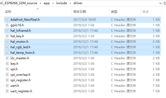
直接下载的NONOS_SDK还需要进行一些修改才能方便我们使用。
driver_lib文件夹中的Makefile文件需要删除third_party文件夹放置了第三方的一些demo,我们这里用不上,因为使用了已经修改好的esp8266_aliyun_mqtt_app,所以也删除- 将
esp8266_aliyun_mqtt_app项目解压至根目录 - 还需修改根目录中的
Makefile,使其符合你的板子
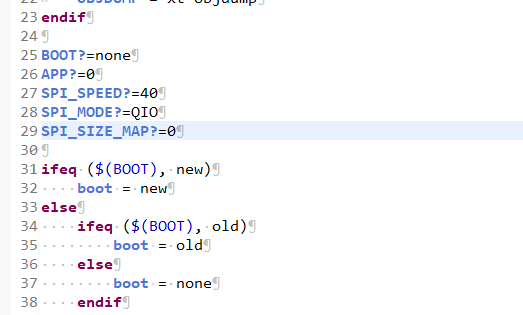
我的修改是:
BOOT?=none
APP?=0
SPI_SPEED?=40
SPI_MODE?=QIO
SPI_SIZE_MAP?=4
如果你并不知道这是什么意思,可以看下面的代码,size_map,flash,addr,等等参数,我就不贴出来了,总之能对应上就行。
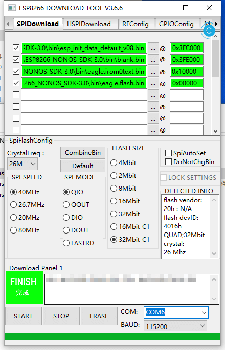
到了这一步,当然可以烧写,看连接情况了,使用NONOS_SDK,就需要手动进行烧写,依然遵循前文所写的烧写地址。
AngelLiang/ESP8266-Demos中的烧写说明
*备注:如果使用 ESP8266 SDK v2.0 以下(不包括v2.0),eagle.irom0text.bin 烧录地址为0x40000。
| bin | 烧录地址 | 说明 |
|---|---|---|
| eagle.flash.bin | 0x00000 | 主程序,编译代码生成 |
| eagle.irom0text.bin | 0x10000 | 主程序,编译代码生成 |
| esp_init_data_default.bin | 0x3FC000 | 初始化射频参数,由 Espressif 在 SDK 中提供 |
| blank.bin | 0x3FE000 | 初始化射频参数,由 Espressif 在 SDK 中提供 |

esp8266_aliyun_mqtt_app中已经为我们做完了一大半的工作,当完成前面的配置和修改后,你的ESP8266已经可以正常连接上阿里云的平台了,如下图所示。

只是连接上,当然还不够,还需继续实现需要的功能。
这次的绝大多数功能代码可以写到ESP8266_NONOS_SDK-3.0\aliyun_mqtt_app\user\user_main.c中。
使用DHT11首先先引用,其他的有需要就自行使用了,不然总会忘记,我总是这样。
//新增外置设备
// #include "driver/hal_infrared.h"
// #include "driver/hal_motor.h"
// #include "driver/hal_rgb_led.h"
#include "driver/hal_temp_hum.h"
接收下发的数据,这一块已经写好了。
在
void mqttDataCb(uint32_t *args, const char *topic, uint32_t topic_len,
const char *data, uint32_t data_len)中。data就是实际的内容。如果只是想测试下简单的内容,则可以直接判断。
if(data[0] == '1')
{
    os_printf("LED status is open... \n");
    PIN_FUNC_SELECT(PERIPHS_IO_MUX_MTDI_U, FUNC_GPIO12);
    GPIO_OUTPUT_SET(GPIO_ID_PIN(12), 0);
}如果想符合平台规则,则要解析JSON,需要使用cJSON。
似乎esp8266_aliyun_mqtt_app中没有Arduino中的loop()函数,自己加上一个就行。我在网上看了下,似乎大家都倾向于服务器端触发,然后在上发数据。但我们的目的就是简单的上发就好了。
在void user_init(void)中是初始化函数,自己的loop,则需要放这里触发。
/** 关闭定时器 */
os_timer_disarm(&os_timer);
/** 配置定时器回调函数 */
os_timer_setfn(&os_timer, (ETSTimerFunc *) ( loop ), &mqttClient );
/** 启动定时器 */
os_timer_arm(&os_timer, 1000, true );其中&mqttClient,是需要传的参数,需要上发消息,当然也可以有其他实现。
还可以初始化GPIO或是加入DHT11的初始化
// 温湿度初始化
dh11Init();
再修改一下波特率,使用115200稍微方便一点。
// uart_init(BIT_RATE_74880, BIT_RATE_74880);
uart_init(BIT_RATE_115200, BIT_RATE_115200);
提到上发,我们使用MQTT_Publish函数。
/*
* MQTT_Publish函数参数说明
* @param  client:         MQTT_Client reference
* @param  topic:         string topic will publish to
* @param  data:         buffer data send point to
* @param  data_length: length of data
* @param  qos:            qos
* @param  retain:      retain
*/
// MQTT_Publish(client, UPDATE_TOPIC, "hello", 6, 0, 0);
还需实现loop,事实上,我写的函数名并不是loop,随便取个好记的吧。
static os_timer_t os_timer;

void loop(uint32_t *args)
{
    MQTT_Client *client = (MQTT_Client *)args;

}
这里的loop就是我们期望循环执行的函数。
加入初始化连接MQTT_Client *client = (MQTT_Client *)args;。
如果期望某段代码不需要每次都执行,而有的需要,可以加个for循环,或是其他方法,在其间来减慢速度。也可以干脆加长整个循环时间。
我们现在就需要来构造上发的JSON,写到loop中。
uint8_t ret = 0;
uint8_t temperature = 0;
uint8_t humidity = 0;

ret = dh11Read(&temperature, &humidity);

char param[32];
char jsonBuf[128];

ets_sprintf(param, "{\"mhumi\":%d,\"mtemp\":%d}", humidity, temperature);
ets_sprintf(jsonBuf, ALINK_BODY_FORMAT, param);

MQTT_Publish(client, THING_TOPIC,jsonBuf,os_strlen(jsonBuf), 0, 0);
ALINK_BODY_FORMAT需要我们先宏定义。
#define ALINK_BODY_FORMAT "{\"id\":\"123\",\"version\":\"1.0\",\"method\":\"thing.event.property.post\",\"params\":%s}"
THING_TOPIC是自己定义的上发地址,和你平台要相同。
#define THING_TOPIC "/sys" BASE_TOPIC "/thing/event/property/post"
使用ets_sprintf进行替换。
不支持浮点数。
如果只是需要测试通联情况,没有实际的传感器设备,则可以使用下面的的代码
// char *random = ("{\"id\":\"123\",\"version\":\"1.0\",\"method\":\"thing.event.property.post\",\"params\":{\"mhumi\":11,\"mtemp\":22}}");
// MQTT_Publish(client, THING_TOPIC,random,os_strlen(random), 0, 0);
总不能发了半天,乱发接口吧。最后还可以释放一下。前面的完成了,再烧写一下差不多是下面这样(没改的)
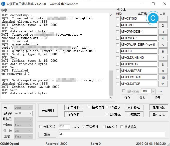
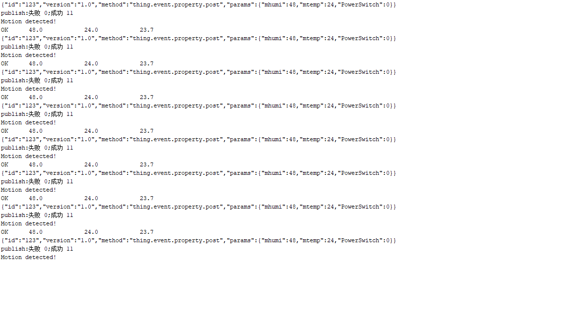
上发的数据是可以打印出来的,差不多是这样,params是自己定义的:{"id":"123","version":"1.0","method":"thing.event.property.post","params":{"mhumi":48,"mtemp":24,"PowerSwitch":0}}
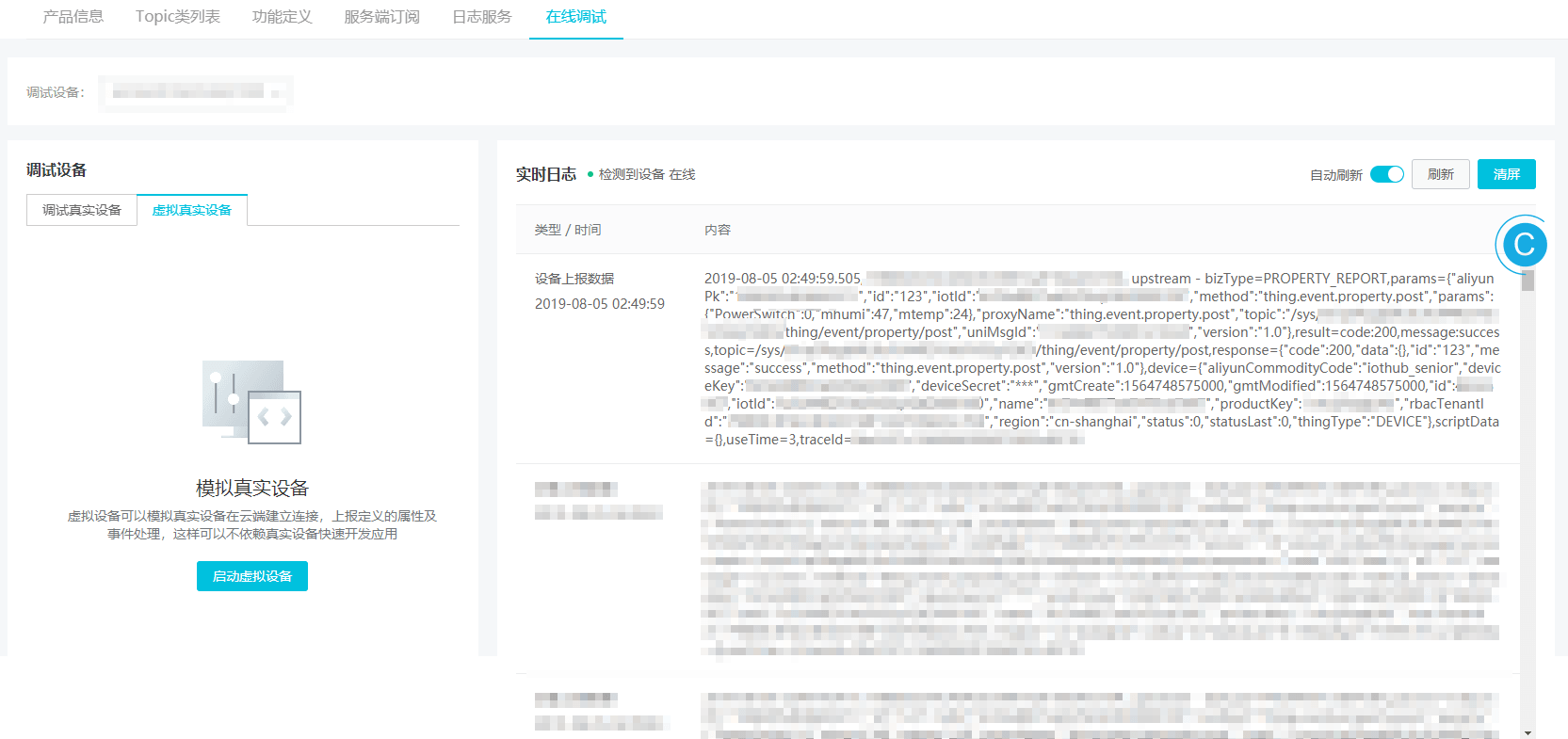
建立一个标准的MQTT DEMO
/*
 Basic ESP8266 MQTT example

 This sketch demonstrates the capabilities of the pubsub library in combination
 with the ESP8266 board/library.

 It connects to an MQTT server then:
  - publishes "hello world" to the topic "outTopic" every two seconds
  - subscribes to the topic "inTopic", printing out any messages
    it receives. NB - it assumes the received payloads are strings not binary
  - If the first character of the topic "inTopic" is an 1, switch ON the ESP Led,
    else switch it off

 It will reconnect to the server if the connection is lost using a blocking
 reconnect function. See the 'mqtt_reconnect_nonblocking' example for how to
 achieve the same result without blocking the main loop.

 To install the ESP8266 board, (using Arduino 1.6.4+):
  - Add the following 3rd party board manager under "File -> Preferences -> Additional Boards Manager URLs":
       http://arduino.esp8266.com/stable/package_esp8266com_index.json
  - Open the "Tools -> Board -> Board Manager" and click install for the ESP8266"
  - Select your ESP8266 in "Tools -> Board"

*/

#include <ESP8266WiFi.h>
#include <PubSubClient.h>

// Update these with values suitable for your network.

const char* ssid = "........";
const char* password = "........";
const char* mqtt_server = "broker.mqtt-dashboard.com";

WiFiClient espClient;
PubSubClient client(espClient);
long lastMsg = 0;
char msg[50];
int value = 0;

void setup_wifi() {

  delay(10);
  // We start by connecting to a WiFi network
  Serial.println();
  Serial.print("Connecting to ");
  Serial.println(ssid);

  WiFi.begin(ssid, password);

  while (WiFi.status() != WL_CONNECTED) {
    delay(500);
    Serial.print(".");
  }

  randomSeed(micros());

  Serial.println("");
  Serial.println("WiFi connected");
  Serial.println("IP address: ");
  Serial.println(WiFi.localIP());
}

void callback(char* topic, byte* payload, unsigned int length) {
  Serial.print("Message arrived [");
  Serial.print(topic);
  Serial.print("] ");
  for (int i = 0; i < length; i++) {
    Serial.print((char)payload[i]);
  }
  Serial.println();

  // Switch on the LED if an 1 was received as first character
  if ((char)payload[0] == '1') {
    digitalWrite(BUILTIN_LED, LOW);   // Turn the LED on (Note that LOW is the voltage level
    // but actually the LED is on; this is because
    // it is active low on the ESP-01)
  } else {
    digitalWrite(BUILTIN_LED, HIGH);  // Turn the LED off by making the voltage HIGH
  }

}

void reconnect() {
  // Loop until we're reconnected
  while (!client.connected()) {
    Serial.print("Attempting MQTT connection...");
    // Create a random client ID
    String clientId = "ESP8266Client-";
    clientId += String(random(0xffff), HEX);
    // Attempt to connect
    if (client.connect(clientId.c_str())) {
      Serial.println("connected");
      // Once connected, publish an announcement...
      client.publish("outTopic", "hello world");
      // ... and resubscribe
      client.subscribe("inTopic");
    } else {
      Serial.print("failed, rc=");
      Serial.print(client.state());
      Serial.println(" try again in 5 seconds");
      // Wait 5 seconds before retrying
      delay(5000);
    }
  }
}

void setup() {
  pinMode(BUILTIN_LED, OUTPUT);     // Initialize the BUILTIN_LED pin as an output
  Serial.begin(115200);
  setup_wifi();
  client.setServer(mqtt_server, 1883);
  client.setCallback(callback);
}

void loop() {

  if (!client.connected()) {
    reconnect();
  }
  client.loop();

  long now = millis();
  if (now - lastMsg > 2000) {
    lastMsg = now;
    ++value;
    snprintf (msg, 50, "hello world #%ld", value);
    Serial.print("Publish message: ");
    Serial.println(msg);
    client.publish("outTopic", msg);
  }
}
使用arduino IDE接入阿里云
我不是很知道官方是不是推荐使用arduino来进行开发的,最起码"看"起来不高端,但是arduino显然是最简单的,因为有包管理器,真说开发,其实代码上差别不大。
NodeMCU(ESP8266)接入物联网平台,官方提供的文档很详细,几乎就是开箱即用了。
说到坑,那肯定是有的,其实还好,不是大问题,只是毕竟是阿里云的,大部分常见的已经被其他同学补上了,前人栽树,后人乘凉。
如果已经使用了官方提供的DEMO,那么,连接平台最重要的工作就是设备认证三元组。
设备认证三元组:ProductKey、DeviceName和DeviceSecret
官方提供了小工具来方便使用,但是并不方便,所以有了第三方的工具,生成MQTT_PASSWD工具。
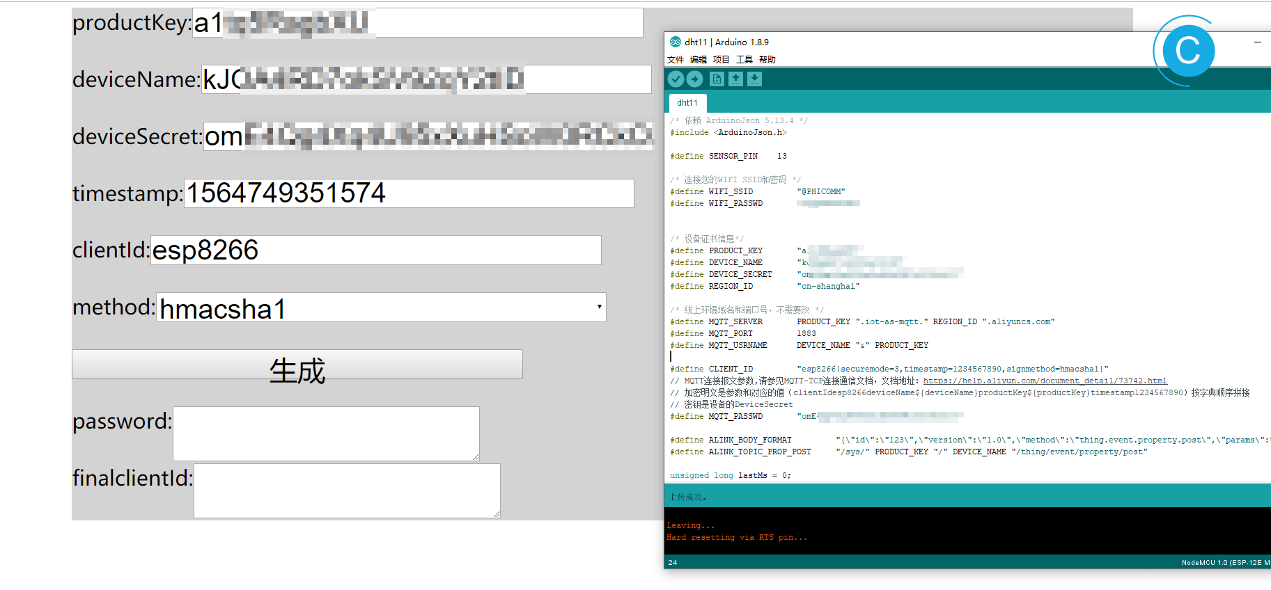
NodeMCU(ESP8266) 接入阿里云物联网平台 踩坑之旅,感谢Lengff12138
如果还遇到了其他问题,则看状态码吧,为了方便我自己查阅,我也引用过来了。
int - the client state, which can take the following values (constants defined in PubSubClient.h):
-4 : MQTT_CONNECTION_TIMEOUT - the server didn’t respond within the keepalive time
-3 : MQTT_CONNECTION_LOST - the network connection was broken
-2 : MQTT_CONNECT_FAILED - the network connection failed
-1 : MQTT_DISCONNECTED - the client is disconnected cleanly
0 : MQTT_CONNECTED - the client is connected
1 : MQTT_CONNECT_BAD_PROTOCOL - the server doesn’t support the requested version of MQTT
2 : MQTT_CONNECT_BAD_CLIENT_ID - the server rejected the client identifier
3 : MQTT_CONNECT_UNAVAILABLE - the server was unable to accept the connection
4 : MQTT_CONNECT_BAD_CREDENTIALS - the username/password were rejected
5 : MQTT_CONNECT_UNAUTHORIZED - the client was not authorized to connect
直接运行
如果你是伸手党,那就直接复制下面的用就好了,人体传感器被我注释掉了。
#include <ESP8266WiFi.h>
/* 依赖 PubSubClient 2.4.0 */
#include <PubSubClient.h>
/* 依赖 ArduinoJson 5.13.4 */
#include <ArduinoJson.h>
/* Use DHT_sensor_library_for_ESPx */
#include "DHTesp.h"

#ifdef ESP32
#pragma message(THIS EXAMPLE IS FOR ESP8266 ONLY!)
#error Select ESP8266 board.
#endif

DHTesp dht;

//define SENSOR_PIN    13

/* 连接您的WIFI SSID和密码 */
#define WIFI_SSID         "路由器SSID"
#define WIFI_PASSWD       "密码"


/* 设备证书信息*/
#define PRODUCT_KEY       "替换为设备的ProductKey"
#define DEVICE_NAME       "替换为设备的DeviceName"
#define DEVICE_SECRET     "替换为设备的DeviceSecret"
#define REGION_ID         "替换为设备所在地域ID如cn-shanghai"

/* 线上环境域名和端口号,不需要改 */
#define MQTT_SERVER       PRODUCT_KEY ".iot-as-mqtt." REGION_ID ".aliyuncs.com"
#define MQTT_PORT         1883
#define MQTT_USRNAME      DEVICE_NAME "&" PRODUCT_KEY

#define CLIENT_ID         "esp8266|securemode=3,timestamp=1234567890,signmethod=hmacsha1|"
// MQTT连接报文参数,请参见MQTT-TCP连接通信文档,文档地址:https://help.aliyun.com/document_detail/73742.html
// 加密明文是参数和对应的值(clientIdesp8266deviceName${deviceName}productKey${productKey}timestamp1234567890)按字典顺序拼接
// 密钥是设备的DeviceSecret
#define MQTT_PASSWD       "f1ef80ee8add322c519a5a6bec326dc499f8****"

#define ALINK_BODY_FORMAT         "{\"id\":\"123\",\"version\":\"1.0\",\"method\":\"thing.event.property.post\",\"params\":%s}"
#define ALINK_TOPIC_PROP_POST     "/sys/" PRODUCT_KEY "/" DEVICE_NAME "/thing/event/property/post"

unsigned long lastMs = 0;
WiFiClient espClient;
PubSubClient  client(espClient);


void callback(char *topic, byte *payload, unsigned int length)
{
  Serial.print("Message arrived [");
  Serial.print(topic);
  Serial.print("] ");
  payload[length] = '\0';
  Serial.println((char *)payload);

}

void wifiInit()
{
  WiFi.mode(WIFI_STA);
  WiFi.begin(WIFI_SSID, WIFI_PASSWD);
  while (WiFi.status() != WL_CONNECTED)
  {
    delay(1000);
    Serial.println("WiFi not Connect");
  }

  Serial.println("Connected to AP");
  Serial.println("IP address: ");
  Serial.println(WiFi.localIP());

  Serial.print("espClient [");

  client.setServer(MQTT_SERVER, MQTT_PORT);   /* 连接WiFi之后,连接MQTT服务器 */
  client.setCallback(callback);
}

void mqttCheckConnect()
{
  while (!client.connected())
  {
    Serial.println("Connecting to MQTT Server ...");
    if (client.connect(CLIENT_ID, MQTT_USRNAME, MQTT_PASSWD))

    {

      Serial.println("MQTT Connected!");

    }
    else
    {
      Serial.print("MQTT Connect err:");
      Serial.println(client.state());
      delay(5000);
    }
  }
}

void mqttIntervalPost()
{
  char param[32];
  char jsonBuf[128];

  //  delay(dht.getMinimumSamplingPeriod());

  int humidity = dht.getHumidity();
  int temperature = dht.getTemperature();

  sprintf(param, "{\"mhumi\":%d,\"mtemp\":%d}", humidity, temperature);
  //  sprintf(param, "{\"mtemp\":%d}", temperature);
  sprintf(jsonBuf, ALINK_BODY_FORMAT, param);
  Serial.println(jsonBuf);
  boolean d = client.publish(ALINK_TOPIC_PROP_POST, jsonBuf);
  Serial.print("publish:0 失败;1成功");
  Serial.println(d);
}

void setup()
{

  //    pinMode(SENSOR_PIN,  INPUT);
  /* initialize serial for debugging */
  Serial.begin(115200);
  Serial.println("Demo Start");

  Serial.println("Status\tHumidity (%)\tTemperature (C)\t(F)\tHeatIndex (C)\t(F)");
  String thisBoard = ARDUINO_BOARD;
  Serial.println(thisBoard);

  // Autodetect is not working reliable, don't use the following line
  // dht.setup(17);
  // use this instead:
  dht.setup(5, DHTesp::DHT11); // Connect DHT sensor to GPIO 17

  wifiInit();
}

// the loop function runs over and over again forever
void loop()
{
  if (millis() - lastMs >= 5000)
  {
    lastMs = millis();
    mqttCheckConnect();

    /* 上报消息心跳周期 */
    mqttIntervalPost();
  }

  client.loop();

  //  if (digitalRead(SENSOR_PIN) == HIGH) {
  //    Serial.println("Motion detected!");
  //    delay(2000);
  //  }
  //  else {
  //    Serial.println("Motion absent!");
  //    delay(2000);
  //  }

  delay(dht.getMinimumSamplingPeriod());

  float humidity = dht.getHumidity();
  float temperature = dht.getTemperature();

  Serial.print(dht.getStatusString());
  Serial.print("\t");
  Serial.print(humidity, 1);
  Serial.print("\t\t");
  Serial.print(temperature, 1);
  Serial.print("\t\t");
  //  Serial.print(dht.toFahrenheit(temperature), 1);
  //  Serial.print("\t\t");
  Serial.println(dht.computeHeatIndex(temperature, humidity, false), 1);
  //  Serial.print("\t\t");
  //  Serial.println(dht.computeHeatIndex(dht.toFahrenheit(temperature), humidity, true), 1);
  delay(2000);
}
还要注意的就是支持库了,不要装错了。
官方使用的是:
- ArduinoJson 构造解析JSON用
- PubSubClient MQTT等连接用
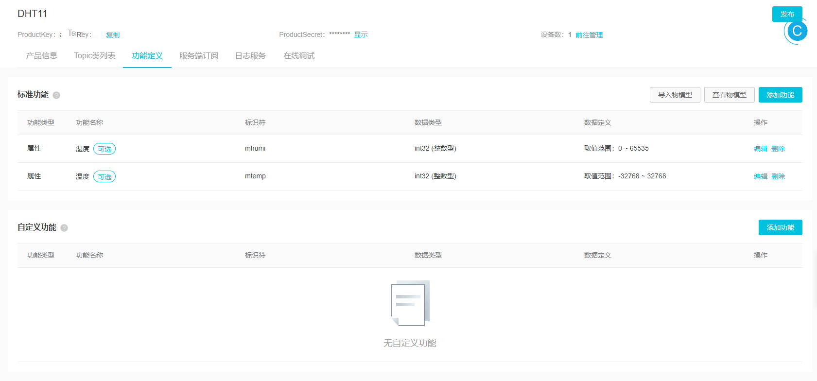
我使用了DHT11/22,用的是:
- DHT_sensor_library_for_ESPx

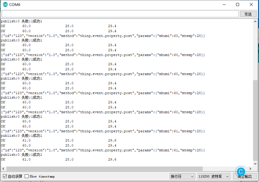

多说几句,可以选择基于TCP的MQTT连接,又分为:两种连接方式:MQTT客户端直连和使用HTTPS认证再连接。
也可以选择MQTT-WebSocket连接通信
使用WebSocket方式进行连接,区别主要在MQTT连接URL的协议和端口号,MQTT连接参数和TCP直接连接方式完全相同,其中要注意securemode参数,使用wss方式连接时securemode=2,使用ws方式连接时securemode=3。
当然,如果你想自行搭建MQTT服务器,那可以使用PubSubClient中的mqtt_esp8266,提供的一个连接MQTT的例程,如果和服务器端依然是约定的使用JSON来进行连接,那依然要引用ArduinoJson,如此一来,在下文中的搭建服务器时,你就可以使用Arduino IDE来进行开发,算是降低了部分难度吧。
附录-运行DHT11/22 DEMO
当然你为了确定前面的设备有没有问题,也可以直接运行下官方Demo,为了方便我就直接贴出来了。
#include "DHTesp.h"

#ifdef ESP32
#pragma message(THIS EXAMPLE IS FOR ESP8266 ONLY!)
#error Select ESP8266 board.
#endif

DHTesp dht;

void setup()
{
  Serial.begin(115200);
  Serial.println();
  Serial.println("Status\tHumidity (%)\tTemperature (C)\t(F)\tHeatIndex (C)\t(F)");
  String thisBoard= ARDUINO_BOARD;
  Serial.println(thisBoard);

  // Autodetect is not working reliable, don't use the following line
  // dht.setup(17);
  // use this instead:
  dht.setup(17, DHTesp::DHT22); // Connect DHT sensor to GPIO 17
}

void loop()
{
  delay(dht.getMinimumSamplingPeriod());

  float humidity = dht.getHumidity();
  float temperature = dht.getTemperature();

  Serial.print(dht.getStatusString());
  Serial.print("\t");
  Serial.print(humidity, 1);
  Serial.print("\t\t");
  Serial.print(temperature, 1);
  Serial.print("\t\t");
  Serial.print(dht.toFahrenheit(temperature), 1);
  Serial.print("\t\t");
  Serial.print(dht.computeHeatIndex(temperature, humidity, false), 1);
  Serial.print("\t\t");
  Serial.println(dht.computeHeatIndex(dht.toFahrenheit(temperature), humidity, true), 1);
  Delay(2000);
}
附录-无需编程的图形化客户端开发
很有意思的IoT Studio,为无需编程开发简单的客户端提供了另外的一种选择。


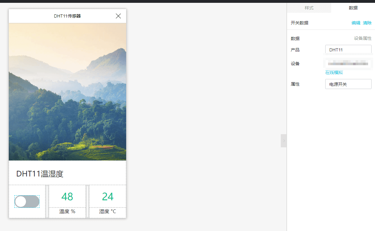


后记
为什么ESP系列的板子好玩,能够不断吸引人来使用,我觉得这个意思就意思在WIFI(能联网)的普遍性和难易程度上,能使用TCP等连接方式,单片机也可以使用W5500来有线连接网络,谁更方便呢。外算上价格低吧。我不太确定有没有专门的文章来谈论这个,就算是有,也无需看了,显而易见的。

总不能说就亮了个灯,操作了继电器吧,能写完还是写完吧。
本作品采用 知识共享署名-相同方式共享 4.0 国际许可协议 进行许可。